Eye muscles will move the cursor on the computer screen while jaw muscles will be used to click. Voice recognition will be used as command shortcuts and as access to programs.

Thursday, May 23, 2013

Amplifier Testing

Week 8

   With our amplifier constructed, we began testing if it can pick up EMG signals. Alligator clips were used to connect the capacitors to the electrodes. The black alligator clip was used for negative electrode A and the red alligator clip was used for positive electrode A. Another alligator clip was used for the reference electrode. The amplifier would transmit signals to the data acquisition board, which is then brought into the computer.


Figure 1 : Amplifier, Data Acquisition Board, and Electrode Configuration

  We used muscles of the forearm to see if the amplifier would pick up the signal. One electrode was placed on the belly of the muscle and the other electrode was place on the end of the muscle. The reference electrode has to be placed on another muscle, far from this forearm muscle. The other end of the alligator clip for the reference electrode, however, had a rounded end instead of a clip. So, an electrode couldn't be used. A group member had to hold the rounded end with his fingers, transmitting signals from muscles from the finger as a reference. Luckily, this was merely used for testing the amplifier, and a proper alligator clip can be used later. As the group member with the electrodes clenched his forearm, the amplitude of the signal increased. As the forearm muscle relaxed, the amplitude decreased.

  DJ explained to us how the EOG and EMG signals should look by sketching them out. Ideally, the signals would instantly rise when the eyes look to the right, then sharply fall when the eyes return to center. The signals would also instantly fall when the eyes look to the left and sharply rise when the eyes return to center. But, in actuality, the signal would slowly fall or rise back to center, even if the eyes are still looking right or left. EMG signals will show little activity with a relaxed muscle and will show large amplitude and high frequency with a contracted muscle. We would need to portion out a section of the signal and create a threshold to determine if the muscle has contracted or not.


Figure 2 : DJ's EOG and EMG Signal Sketches


Tuesday, May 21, 2013

Speech Recognition MATLAB Coding

Week 7

   We worked on coding for our speech recognition program, using MATLAB. Additional toolboxes, specifically the signal processing toolbox, needed to be downloaded for use with MATLAB.

  We continued using a source that can be found in week 3's post (the third source). Several MATLAB source files are given. The source file for testing the incoming voice commands calls the matching function, which in turn calls the extracting function. The extracting function returns a vector for the input. The training function also calls for extraction. However, the main source file of the word recognition programs is for speech. It calls the other functions (recording, training, extracting, testing, and matching) and keeps track of the vocabulary that is trained into the program.

  While running these source files in their original form, some errors occurred with loading data into the MATLAB workspace. Adjustments in the code have to be made to suit our needs. This includes having code to tell the computer what to do once it recognizes a word. The original program only recognizes and classifies what the user has said.

Sunday, May 12, 2013

Redo resistors

Week 6

   Our new circuit board allowed for more space between the amplifier and the capacitors and resistors. We put our components on the top of the circuit board, just in case more mistakes arise (we could always use the bottom of the circuit board).

  Despite the new circuit board, we kept our redesign with the wires. Blue wire was still used for connecting the resistor and capacitor to the amplifier. Yellow wire was used to connect the other resistors to the Data Acquisition Board. A green wire went around the circuit board to act as ground.

  When we tested the resistance, we realized we used the wrong resistors. The resistors we were using with the capacitors yielded 47 Ohms, but we needed a resistance of 47 k Ohms (see schematic from week 4 post). So we got new resistors with 47 k Ohms, soldered off the original resistors and soldered in the new ones.


Figure 1: Wrong Resistor (47 Ohms)
Color Bands: Gold, Brown, Black, Orange, White


Figure 2: Right Resistor (47 k Ohms)
Color Bands: Yellow, Black, Orange, Gold

Saturday, May 4, 2013

Circuit Board Redesign

Week 5

   The soldering of the capacitors and resistors proved troublesome. The ends of the capacitors were soldered together and to the resistors. So, we removed the capacitors, resistors, and amplifier from the circuit board and rethought our design. 
   
   A problem with the original design was that it lacked space. There was little room between the capacitors, resistors, and amplifier. This led to the accidental soldering. To allow more space, we implemented the use of wires to join the resistors and capacitors to the amplifier. The battery leads' wires were long enough to not need additional wire. A concept sketch of this design can be seen below:

Figure 1: Circuit Board Redesign Sketch

    Different colored wires will be used to tell the function of each wire. Blue wires are for electrodes and the RGA resistor. There will also be yellow and black wires. We have not decided what roles those colors will represent yet.

Figure 2: Circuit Board Redesign in Progress

  More circuit board troubles came later in the week. We realized that both ends of capacitors were soldered together. We also learned that the copper on the circuit board provides the connection between components, so we didn't have to solder parts directly together. Each component on the same horizontal row of copper (in the center) would be connected together. Each component on one of the 2 vertical columns of copper (on the sides) would be connected together. This leads to more room and less occurrences of accidental connections. A new circuit board will be bought, since there's too much solder on the current one. This new one will be a bigger model, to make room for any future mistakes. We may also use one of our extra amplifiers, since our current amplifier has been through a lot and may have burnt out.


Tuesday, April 30, 2013

Amplifier Construction

Week 4

   During the week 4 lab, we learned how to use a soldering iron. Intense heat is used to connect metal portions of wires and other electrical components together. Using this knowledge, we started on the mechanical construction portion of our project, specifically the instrumentation amplifier. DJ gave us a schematic to follow, which can be seen below as Figure 1.


Figure 1: Instrumentation Amplifier Schematic

   We focused mainly on soldering the capacitors, resistors and amplifier onto the circuit board first. We had to compensate for the lack of space on the circuit board. There wasn't much surface area on the circuit board to allow adequate space between the resistors and capacitors. We also had to be careful to not solder the positive and negative ends of the resistors together. 

   As seen in the schematic, some resistors (R1, R2, R3, R4) and reference electrodes (REFA and REFB) will need to go to ground. So, we thought about putting a wire around the circuit board to act as ground.


Figure 2: Circuit Board in Progress


Sunday, April 21, 2013

Mechanical Parts, FAQ, and Voice Recognition

Week 3

    We decided to order small sized Nikotab 0X15 tab electrodes (No. 0315, 21 x 34 mm), since there is a lack of surface area around the eye area. We also obtained a data acquisition box (the USB-6009). This will be programmed in MATLAB. We also answered questions presented to us by DJ, explaining physiology of EMG/EOG. These answers can be seen on our FAQ page.

   We also worked on the word recognition part of our project. We decided that the activation and deactivation of the recording process will be signaled by stating keywords. This would eliminate the need to continuously record, since that would take up memory. The voice recordings will then be processed and plotted on a graph. To have the word program decide on what the speaker said, the newly plotted graph will be compared with previously plotted graphs, made by previously recorded words. If the current plot graph is matched, then the program will deduce that the user said the phrase relative to the matching plot graph.

   From there, we delved into research on MATLAB code that would enable a word recognition system. Here is a link to our first finding: http://www.mathworks.com/tagteam/60673_91805v00_WordRecognition_final.pdf
This gave us a template for our workflow and for our MATLAB program. There are several stages to our program; the first one is training. This is when we record the user saying a single command, such as "save document," several times. We will then capture 10 seconds of this speech from the computer's built-in microphone at 8000 samples per second. The next stage, testing, will require acquiring previously recorded speech samples while processing incoming speech. The Data Acquistion Toolbox will be used to perform this function. Graphs of the speech samples will be made. This link also mentioned Mel Frequency Cepstral Coefficients (MFCCs) that give a measure of the energy within overlapping frequency bins of a sound spectrum. Using this, MFCC vectors can be calculated from the test speech and incoming speech, and be compared.
. We also found another source: http://www.ece.iit.edu/~pfelber/speechrecognition/report.pdf. This article explains Linear Predictive Coding (LPC) that can extract and store information about the points of loudness (formants) in the sound spectrum. We can use LPC to compare the formants of the stored speech and incoming speech. This article also gives MATLAB source files for extracting, matching, recording, speech, training, and testing. We also found a simple MATLAB code for recording and plotting audio samples, which can be seen in Figure 1. We can use this code, along with the code found in the previous sources, as a starting point to creating our own word recognition program.


Figure 1 :  MATLAB code for recording and plotting audio samples.


Figure 2 : Plot graph of the the phrase "save document," using MATLAB code from Figure 1.


Resources:
[1] N.p. (n.d.). Developing an Isolated Word Recognition System in MATLAB. (N/A) [Online]. Available: http://www.mathworks.com/tagteam/60673_91805v00_WordRecognition_final.pdf

[2] N.p. (n.d.). Record and Play Audio. (N/A) [Online]. Available: http://www.mathworks.com/help/matlab/import_export/record-and-play-audio.html#bsdl2em

[3] P. Felber.(2001, April 25). SPEECH RECOGNITION
Report of an Isolated Word experiment
. (N/A) [Online]. Available: http://www.ece.iit.edu/~pfelber/speechrecognition/report.pdf.


Tuesday, April 16, 2013

Shortcut Functions and Facial Muscles


Week 2

   After a talk with DJ, we decided to be more specific with what commands we would want to implement into our program. We were inspired by pre-existing keyboard shortcuts used for windows. Examples of these commands can be seen here: http://windows.microsoft.com/en-us/windows7/keyboard-shortcuts . We decided to include shortcuts for functions such as:


  • “Open/Close programs, including Internet Explorer, Microsoft word, Windows media player, iTunes,  and will include an option to add other desired programs
  • “Save Document”
  • “Undo” or “Redo”
  • “Zoom in/out”
  • “Stop voice commands”
  • “Search for file"

 
These functions and commands will allow users to gain much of the functionality of the keyboard for shortcuts and improve the interface and ease of use. We plan to implement this by having responses to prompts be stored, then compared to the different voice commands given by the user, and then the command that is recognized by the speech recognition program will be activated through a section of code that can interact with the operating system. In light of these changes and modifications to the project direction, the group reworked the topic proposal to fit these changes.
         
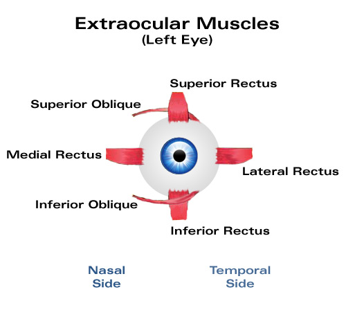
           We also did some research regarding eye and jaw muscles to figure out what happens during the movement of those muscles. The information we gathered would let us deduce where the best placement for the electrodes would be. There are 6 extraocular muscles that turn the eye about its vertical, horizontal, and antero-posterior axes. There are also cardinal positions (positions of gaze) which allow comparisons of horizontal, vertical, and diagonal movement. The muscle of one eye is "yoked" with a muscle of the other eye when put in these positions. So, we will place the electrodes on top, bottom, and side of the eye to detect these muscle movements.

Figure 1: Extraocular Muscles

For the jaw, the masseter muscle closes the jaw. It is located on the sides of the jaw. Electrodes will be placed here to detect the clenching of the left/right jaw. The anterior belly of the digastric muscle opens the jaw. It's located on the chin. We will place an electrode here to detect when the jaw opens, activating the voice recording.

Figure 2: Jaw Muscles (Masseter and Digastric Anterior Belly)

     We also started ordering and gathering parts for the device. There is a list of those parts outlined in the project proposal page


References:

[1] N.p. (n.d.). Keyboard shortcuts. (N/A) [Online]. Available: http://windows.microsoft.com/en-us/windows7/keyboard-shortcuts
[2]N.p. (n.d.). Muscles that move the lower mandible (the jaw). (N/A) [Online]. Available:
http://linguistics.berkeley.edu/~kjohnson/ling110/Lecture_Slides/6_MotorControl/face_tongue_muscles.pdf
[3]  N.p. (n.d.). Science of massage. (N/A) [Online]. Available: http://www.scienceofmassage.com/dnn/som/journal/1007/tmj-f7.jpg
[4] T.M. Montgomery. (n.d.). The Extraocular Muscles. (N/A) [Online]. Available: http://www.tedmontgomery.com/the_eye/eom.html